If you’ve ever worked with piping systems in industrial setups—whether it’s manufacturing, petrochemical processing, water treatment, or energy production—you know that even a millimeter of misalignment can turn a simple installation into a costly headache. As a JIS flange supplier with over 12 years of hands-on experience working with clients across North America, Europe, and Southeast Asia, I’ve seen firsthand how rushing the installation of these standardized flanges leads to everything from leaking joints and reduced flow efficiency to full system shutdowns that cost thousands of dollars in lost production. The good news? Adjusting the installation position of JIS flanges doesn’t have to be a guesswork job. With the right tools, techniques, and a deep understanding of JIS B2220 standards—the core specification that governs JIS flange dimensions, pressure ratings, and bolt hole patterns—you can achieve an accurate, leak-free fit that will stand up to the pressures and cycles of daily operation. Today, I’m breaking down the step-by-step process we’ve refined over the years to help our clients get this right on the first try. Jis Flange
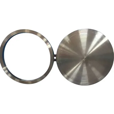
First, let’s pause to make sure we’re all on the same page about why JIS flange positioning is so critical. JIS flanges, unlike their ANSI or DIN counterparts, are designed to strict Japanese Industrial Standards, with specific bolt circle diameters, outside diameters, and pressure classes (like 5K, 10K, 16K, and 20K) that must align perfectly with the mating pipe, valve, or equipment. A 1mm offset between bolt holes, for example, can make it impossible to thread bolts without cross-threading, which damages both the flange and the bolt, creating a weak point that will leak under operating pressure. Even worse, angular misalignment—where one flange is tilted relative to the other—can cause stress in the piping system that leads to fatigue cracks over time, resulting in unplanned repairs or safety hazards. That’s why taking the time to adjust the flange’s position accurately isn’t just a best practice—it’s a requirement for compliance with industrial safety regulations and long-term system reliability.
The first step before any adjustment is preparation, and this is where many teams cut corners. Before you even pick up a wrench or a measuring tape, you need to verify the components you’re working with are compatible. Start by cross-checking the JIS flange’s markings: every legitimate JIS flange will have a stamped marking indicating its pressure class (e.g., 10K), nominal pipe size (NPS 2, 4, etc.), and the JIS standard number. If the marking is faded or missing, it’s a sign the flange may be counterfeit or non-compliant, which will make accurate positioning nearly impossible. Next, confirm that the mating pipe or component matches the JIS flange’s bolt pattern and outside diameter. For example, a JIS 10K 4-inch flange has a bolt circle diameter of 184mm and 8 bolt holes spaced evenly around that circle; if the pipe you’re connecting has a different bolt circle, you’ll need to use a reducing adapter or replace the pipe before adjusting the flange position. Another key prep step is cleaning the sealing surfaces of both the existing flange and the mating component. Any rust, weld slag, or residual gasket material on the sealing face can throw off your measurements and create a gap that’s hard to eliminate during adjustment. We always recommend using a wire brush or a surface grinder to remove debris, then wiping the surface with isopropyl alcohol to ensure a smooth, uniform surface.
Now, let’s get to the actual positioning and adjustment. The most reliable method we teach our clients involves three core tools: a dial indicator, a flange alignment fixture (or a set of feeler gauges), and a tape measure or laser distance measurer for quick checks. Start by temporarily placing the JIS flange on the end of the pipe, but don’t weld or bolt it down yet. Next, use your dial indicator to check for runout—this is the measure of how much the flange’s face deviates from a perfectly flat, perpendicular plane to the pipe’s axis. Position the dial indicator’s tip against the outer edge of the flange’s sealing face, then rotate the flange slowly by hand. If the indicator shows a variation of more than 0.5mm (for pressure classes above 10K, this threshold drops to 0.3mm), the flange is not perpendicular to the pipe, and you’ll need to adjust its position. This adjustment is done by gently tapping the flange with a soft mallet (never a steel hammer, which can dent or damage the sealing face) while monitoring the dial indicator. Make small, incremental taps, checking the reading after each one, until the runout is within the JIS standard’s allowed tolerance—typically ±0.2mm for most industrial applications.
Once the flange is perpendicular to the pipe, the next step is to adjust its axial and rotational position to align with the mating component. Rotational misalignment is the most common issue here, where the flange’s bolt holes don’t line up with the holes on the valve or equipment you’re connecting to. To check this, hold a straightedge across the two flanges and measure the gap between the straightedge and each flange face at multiple points around the circumference. If the gaps are uneven, rotate the JIS flange slightly until the gaps are as uniform as possible. For precise rotational alignment, many of our industrial clients use a bolt hole alignment tool—this is a simple guide that slides over both flanges to line up bolt holes, or a laser alignment device that projects a line through the center of both flanges to ensure they’re concentric. If there’s a slight offset in the bolt holes that can’t be corrected by rotation (say, 1mm or less), you can use a stainless steel oversize bolt or a flange alignment spacer, but these should only be used as a temporary fix. For permanent installations, it’s better to rework the pipe or component to match the flange’s bolt pattern, as spacers can create additional stress points over time.
Axial alignment is the third and often overlooked part of accurate flange positioning. This refers to how close the two flanges are to each other, with the correct gap being determined by the type of gasket you’re using. For a flat gasket, the ideal gap is equal to the gasket’s thickness; for a ring joint gasket (used for high-pressure JIS flanges above 16K), the gap should be slightly less than the gasket’s height to ensure a tight seal when bolts are tightened. To adjust the axial position, you can either push or pull the flange along the pipe—if the pipe is welded, you may need to use a flange puller to create a small gap before adjustment. Once you’ve set the gap, use feeler gauges to check the distance between the two flanges at four or eight evenly spaced points around the circumference. The gap should be within ±0.1mm of the desired distance to ensure even bolt tension when you tighten the bolts. A common mistake here is leaving too large a gap, which causes the gasket to compress unevenly and leak, or too small a gap, which damages the gasket or causes the flanges to bend when bolts are tightened.
After you’ve aligned the JIS flange perfectly, the final step is securing it correctly—this is where poor installation often undermines all your hard work. Start by hand-threading all bolts into the flange holes to avoid cross-threading, then use a torque wrench to tighten the bolts in a crisscross pattern (never in a circle). For example, if you have 8 bolts, tighten bolt 1 first, then bolt 5, then bolt 3, then bolt 7, and so on. This ensures that tension is applied evenly around the flange, preventing it from shifting out of alignment. The torque specification for JIS flange bolts is listed in JIS B2220, based on the pressure class and bolt size—for a 10K 4-inch flange, for instance, M16 bolts should be tightened to approximately 80 Nm. After tightening, double-check the alignment with your dial indicator and straightedge to make sure no shifting occurred during bolting. If you’re working with high-temperature or high-pressure systems, we recommend doing a second torque check after the system has been run at operating temperature and pressure, as thermal expansion can cause the flange to shift slightly.

As a JIS flange supplier, we’ve seen how even small misalignment errors can derail an entire project, but we also know that with the right process, these issues are completely avoidable. If you’re working on a large-scale project or dealing with a complex piping system, don’t hesitate to reach out with questions or for technical guidance—our team has years of experience supporting installers and engineers across industries, and we’re happy to share tips tailored to your specific application. Whether you need help verifying JIS flange specifications, selecting the right flange for your pressure class, or troubleshooting alignment issues, we’re here to make sure your installation is accurate, compliant, and reliable.
Forging References
- Japanese Industrial Standards Committee. JIS B2220: Steel Flanges. Tokyo: Japanese Standards Association, 2018.
- Fluid Sealing Association. Pipe Flange Alignment and Installation Best Practices. Philadelphia: Fluid Sealing Association, 2021.
- American Society of Mechanical Engineers. Piping Systems and Pipeline Components: Flange Design and Installation. New York: ASME International, 2020.
Shanxi Xinshunda Flange Manufacturing Co., Ltd.
As one of the most professional jis flange manufacturers and suppliers in China, we also support customized service with competitive price. We warmly welcome you to wholesale high quality jis flange for sale here from our factory. For quotation, contact us now.
Address: Zhunagli Industrial Zone,jinchang Town,dingxiang,shanxi,china
E-mail: sales01@xinflange.com
WebSite: https://www.xinflange.com/
